
This essay describes autogyros and how they work, gives a brief history of their early development, explains their differences with other aircraft, and explains why they were never accepted. It then explains some modern autogyro concepts.
The original version of this paper was written for a school project in 1996. I originally published it online because there wasn't any information about autogyros on the Internet at the time. As I have learned more about the subject, I have made a few updates to this paper, but the history section still leaves out some important people and projects (such as Harold Pitcairn, W. Wallace Kellett, the McDonnell XV-1, and the Fairey Rotodyne, to name just a few). However, as the Internet has also grown in that time, much of this information is now available. So, rather than completely overhaul this essay, I will direct readers to the References, Related Links, and Additional Information sections at the end of this page, should you wish to learn more than what is presented here.
For archiving purposes, older versions of the essay can be found here.
A reader, Runald Meyer, has translated this essay into German. I can't understand German, so I can't vouch for the accuracy, but the essay is available here:
German Translation (Deutsche Übersetzung)
Autogyros are an aircraft that have been around for decades. In addition to the name autogyro, they have been known as gyrocopters, gyroplanes, and autogiros. They were the first rotary wing aircraft to fly successfully with sufficient control. The design had inherent safety, better low-speed flight than airplanes, as well as the capability of vertical take-off and landing. But despite their advantages, even before the introduction of the first successful helicopters which surpassed their performance, autogyros were never accepted. This paper will explain how autogyros work in order to give the reader a better understanding of the machine, go over the advantages and disadvantages autogyros have over airplanes and helicopters, go over a brief history of the development of the autogyro, and using all this information attempt to explain why autogyros were never accepted. The paper will then discuss where autogyros stand in the aviation world today.coque telephone aesthetichttps://www.thijsal.com/shop/
How Autogyros Work
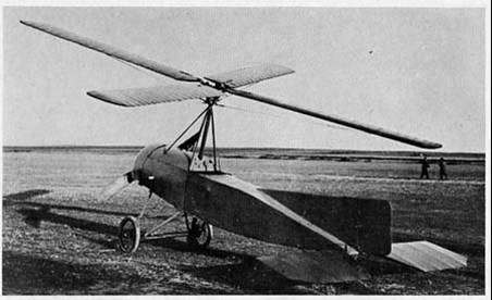
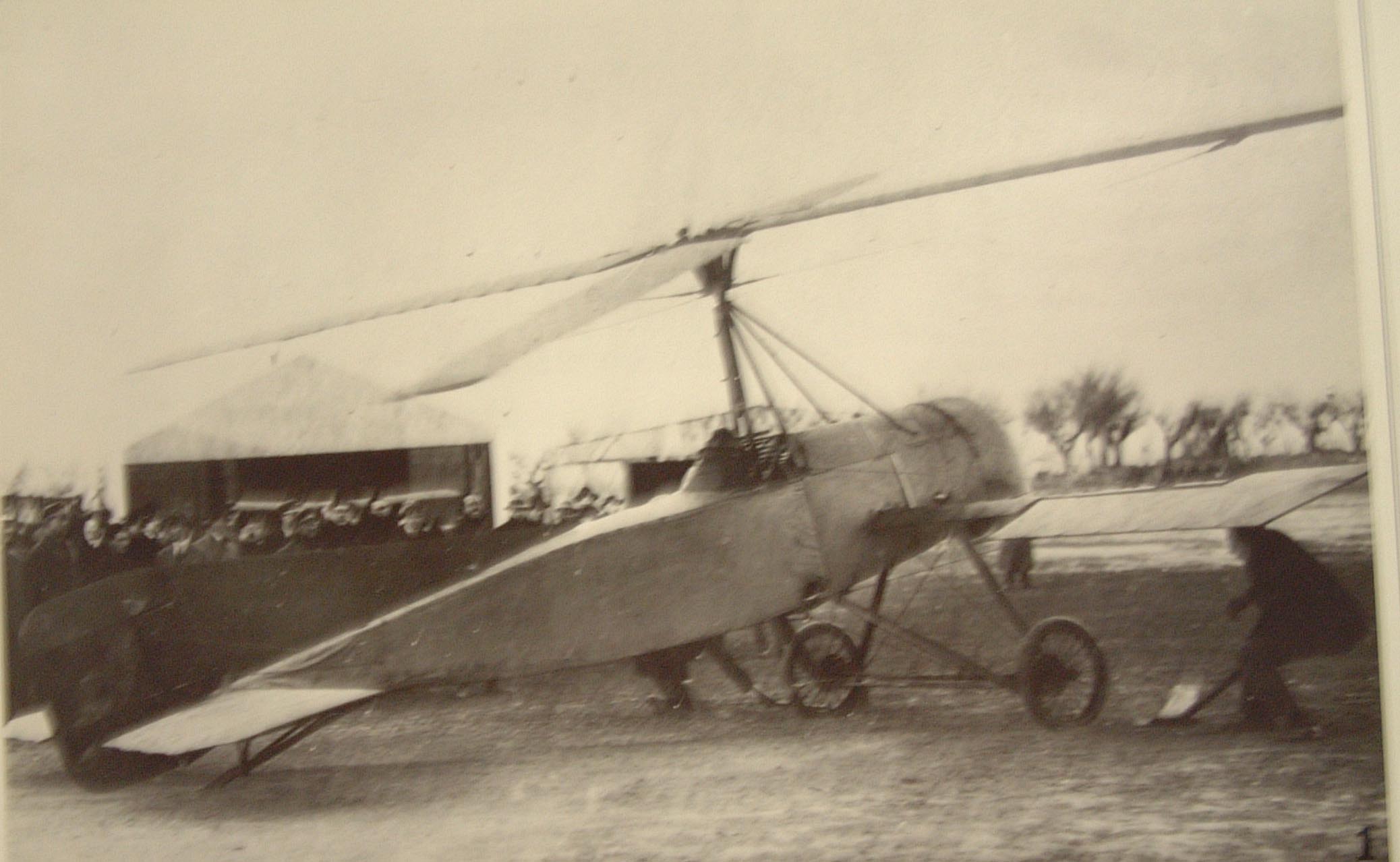
Pitcairn PA-36 Whirlwing Autogyro
An autogyro is a flying machine. Like a helicopter, it is a rotary wing aircraft- which means that it has a rotor to provide lift instead of wings like conventional airplanes. Unlike a helicopter, the rotor is not powered by the engine. It is made to spin by aerodynamic forces, through a phenomenon called autorotation. Since the rotor is not powered, an autogyro needs a separate source for propulsion, like an airplane. Conventionally, these have been propellers, but it's possible to use jet engines as well.
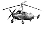
Now what causes the rotor to spin, or "autorotate?" The simple explanation is that the wind passing through it gives it its power. Think of those seed pods that spin as they fall. As they fall, the air makes them spin. (Because they're spinning, it's as if the mini wing was moving faster, so it creates more lift, and the seed pod doesn't fall as fast as it would if it didn't spin.) For a more technical explanation, take a look at the vector diagram below. It shows a rotor in autorotation. A detailed explanation is in the paragraph that follows.
Vector Diagram of Autorotation
(Open in new window)
The vector diagram above illustrates autorotation. (The author has received several e-mails from people confused by these diagrams, so please note: The main diagram, and the diagram in the lower right have been rotated such that the plane of rotation forms the horizontal axis. The actual orientation of the rotor is illustrated in the small diagram in the top right.) The diagram in the lower right shows the winds relative to the rotor. Since the rotor is spinning, there will be relative wind due to this spin, which is labeled as Relative Wind due to Rotor. The Relative Wind due to Aircraft Movement is due to the fact that the aircraft is moving forward, and the rotor is mounted in such a way that the plane of rotation is at a slight angle to the direction the aircraft is moving in. The sum of these two vectors is the relative wind to the airfoil, and is labeled as Resultant Relative Wind. The main diagram shows a cross section of the rotor at a point in time where it is moving forward relative to the aircraft. The Resultant Relative Wind from the smaller diagram is shown on this as the Relative Wind. Any wind passing over an airfoil will create both lift and drag. The lift will be perpendicular to the airflow, and the drag will be parallel to the airflow. This is true for all airfoils, not just for the rotor in an autogyro. (For a description of how wings work, check out my page on how planes fly.) When the lift and drag vectors are added together, they create a Resultant Force. In autorotation, this resultant force is in front of the Axis of Rotation, so in addition to providing lift, it also pulls the rotor forward. This is in sharp contrast to the rotor of a helicopter in forward flight. A helicopter gets its propulsion by tilting the rotor forward. This angles the lift forward, giving the helicopter forward propulsion.
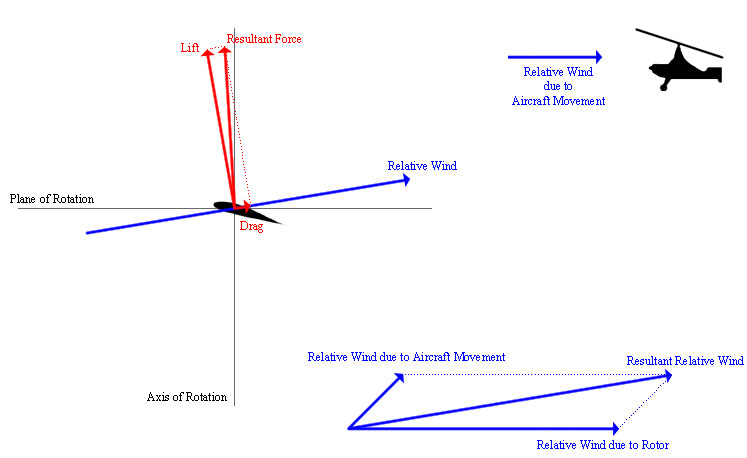
Vector Diagram of a Helicopter Rotor in Forward Flight
(Open in new window)
However, this makes the relative wind due to the aircraft movement move down over the rotor instead of up through it as in an autogyro. The vector diagram above, which is the exact format as the other and uses the same labels, shows the results of this different relative airflow. Instead of pulling the rotor forward, it actually holds the rotor back.
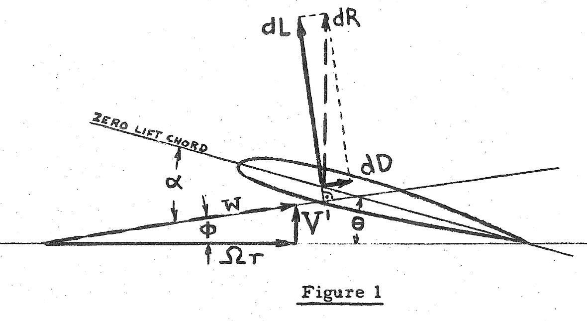
The above is the simpler explanation, and most people may just want to skip ahead to the next section. But the curious reader may still be wondering a few things - those diagrams only show the blade facing in one direction, what happens on the retreating blade? Does it make a difference what part of the rotor is being examined? Those questions can be answered by looking at different stations on the rotor blade. The following two diagrams were taken from a technical report detailing how to calculate various aspects of rotorcraft performance. (The author apologizes for not knowing the source - he received an excerpt in an e-mail, and knows only that the diagrams are from pages 137 & 141 of Chapter VIII, Autorotation, but not the name or author of the report.) These diagrams were actually drawn for the specific case of a straight vertical descent, with no forward airspeed. If the aircraft was traveling forward, the V' vector in the first diagram would be a little different, but very similar results, especially in a qualitative sense, would still be obtained.
This first diagram is a detailed vector diagram of the forces at one section of the blade. It is similar to the simpler ones from above, but incorporates the forces and velocities into one diagram.
Generic Vector diagram of Forces on Blade Section
(Open in new window)
where:
dL → incremental lift force
dD → incremental drag force
dR → incremental resultant force
ΩT → velocity due to rotor spinning
V' → velocity of aircraft
w → resultant velocity at element
θ → angle of blade relative to plane of rotation (collective)
Φ → change in angle due to aircraft velocity
α → angle of attack
Note that ΩT, the velocity due to the rotor spinning, will be different depending on where on the rotor it's being measured. ΩT will be greatest at the tip of the rotor, and will be zero at the axis of rotation. Keeping that in mind, the following diagram shows how the relative velocity, w, changes at different stations of the blade, and the effect that has on the airflow.
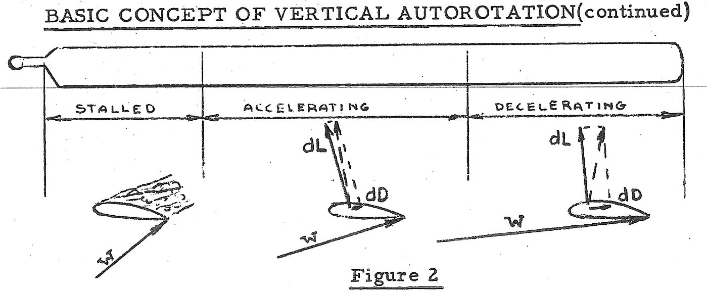
Generic Vector diagram of Forces on Blade Section
(Open in new window)
In towards the very root, the angle of attack will likely be too high, and the blade will be stalled in that region. A little further out on the blade, the resultant force will be ahead of the axis of rotation, and will try to accelerate the rotor, while towards the tip, the resultant force will be behind of the axis of rotation, and will try to slow the rotor. In steady flight, the accelerating and decelerating forces on the rotor will cancel each other out, and the rotor will stay spinning at a given rpm. As conditions on the rotor change (as the pilot performs a maneuver), the rotor may speed up or slow down, but will eventually find an equilibrium at a new rpm.
Note that if there were some forward velocity, the vector, V', would no longer be straight up. This would reduce the angle of attack on the advancing blade (the one moving forward relative to the aircraft), and increase the angle of attack on the retreating blade (the one moving backward relative to the aircraft). That would have the effect of shifting the regions depicted above inboard on the advancing blade, and shifting them outboard on the retreating blade.
Differences Between Autogyros and Other Powered Aircraft
Now that it is known how an autogyro works, it will be easier to understand the advantages and disadvantages the autogyro has compared to airplanes and helicopters. When comparing an autogyro to an airplane, an autogyro has two distinct advantages, first the area it needs to take off and land, second is its low speed flight characteristics. Autogyros do not require as much area to take off and land as do airplanes. Early autogyros required only about 50 feet of runway to take off and could land in under twenty when airplanes were using hundreds of feet. Later autogyros reduced their need for a runway to less than fifteen feet, and eventually to vertical take off and landings. This allows autogyros to be flown from practically anywhere, needing almost no runway. In fact, in the 1930's and 40's, autogyros were used to carry mail from post office rooftops in Camden, NJ, Philadelphia, PA, Chicago, IL, New Orleans, LA, and Washington, D.C., as well as other cities in the north east.
The other main advantage autogyros have over airplanes is their ability to fly slow and not stall. The amount of lift generated by an airfoil is proportional to the relative speed at which it moves through the air, and to the angle at which it's moving through the air (angle of attack). However, once you try to go above a certain angle, there is a sharp decrease in the amount of lift the wing makes. This is known as stall, and is caused by the air not being able to change direction fast enough to stay attached to the wing. Since the wings are fixed in an airplane, creating more lift means either moving the whole aircraft faster, or increasing their angle of attack. In an autogyro, the wings are the rotor and are moving through the air at the speed at which the rotor is spinning, not the speed at which the aircraft is moving. The aircraft does have to be moving forward some to maintain the autorotation, but this is a much lower speed than the speed airplanes must maintain to produce lift. Autogyros can fly at speeds as low as 15 mph. Men can run faster than that speed. And unlike low speed airplanes which have huge wings creating enough lift for low speed flight which means a huge increase in drag, autogyros do it with the faster spinning rotor, so autogyros have a larger speed envelope, or they are capable of flying in a greater range of speeds than airplanes.
The other part of an autogyro's advantage flying at low speed is its inability to stall. As an airplane flies slower, it must increase the angle at which it is flying to create more lift. At a certain point, this angle becomes too great, the air stops flowing over the wings smoothly, and the wing stalls. When this happens, the airplane falls, just like dropping a baseball out a window. When an autogyro slows to a speed less than that needed to maintain autorotation, lift is not instantly lost. Instead, the rotor just starts slowing down. Since it's still spinning, it's still creating lift. The result of slowing an autogyro down too much is just that the aircraft will descend gently. It will not fall like an airplane does. But these advantages aren't without drawbacks. Even though the rotors create less drag than the large wings of low speed airplanes, they create more drag than the smaller wings of higher speed airplanes. So, autogyros create more drag than airplanes of comparable size that fly at the same speeds. Also because of this drag, autogyros are not suitable for high speed flight or long distance flight. (Read more about rotorcraft limitations in Rotorcraft Limitations.)
There are also several advantages that autogyros have over helicopters, namely simplicity, speed, and weight. A helicopter rotor must be complex to a certain degree. It provides the lift, thrust, and control for the aircraft. It needs a method for cyclic and pitch control. An autogyro also uses the rotor for control, but it does not need collective control. Some of the more complex autogyros have collective control, but it is not a necessity for the smaller autogyros. This reduces the complexity of the system, and by eliminating controls reduces weight. The weight in an autogyro is also reduced because it does not power the rotor in flight. To power the rotor in flight typically requires that it be connected to the engine through drive shafts and gearboxes. These must be strong enough to handle the torque driving the rotor, and add up to a significant weight. An autogyro does not need these systems, so it can be made lighter. Even if the autogyro has these systems for prerotating the rotor for a jump takeoff, they do not need to be as robust as those in a helicopter because they will not need to handle the same amount of torque, and also because they are not flight critical, they don't need to be overdesigned.
An autogyro can also fly faster than a helicopter. This is due to the fact that the rotor is providing only lift, whereas the rotor in a helicopter is providing both lift and thrust. For a rotorcraft to stay balanced, it must produce the same lift on both the advancing and retreating blades. A more detailed explanation of this is in the history section below. The advancing blade, the one moving with the aircraft, sees a higher velocity than the retreating blade. So, to produce the same amount of lift, the retreating blade must be at a higher angle of attack. Remember from the discussion above that at a certain angle of attack, the blade will stall, and will quit providing lift. This is a limiting factor in both autogyros and helicopters (and is explained in more detail in Rotorcraft Limitations). But because the helicopter must generate more force with its rotor, it will encounter this problem at a lower speed than the autogyro, allowing the autogyro to fly faster.
The helicopter has one major advantage over the autogyro- the ability to hover. By studying the vector diagrams, one can see that the forward movement of the autogyro is necessary for its autorotation, and therefore for sustained lift. As stated before, when the autogyro stops moving forward, it begins to descend. With a skilled pilot, a helicopter can stay in one spot until it runs out of gas. Hovering is an essential ability for many of the roles that helicopters perform, especially rescues. The helicopter needs to hover in one spot to pick up a victim, something which autogyros are incapable of.
There is one other major advantage that autogyros have over airplanes and helicopters- safety in event of an engine failure. If an engine fails in an autogyro, the same thing would happen as if the pilot tried to fly too slow. The aircraft would slowly descend until landing. In fact, the procedure for landing an autogyro after engine failure is the same for landing an autogyro under ordinary circumstances. In an airplane, when the engine fails, the pilot must try to glide the airplane in to a landing. Pilots do train for this, but dead stick landings require more skill, and an airplane still needs a runway to land. The pilot must search for an area large and smooth enough to land the airplane, close enough to get to before the plane crashes. Helicopters are also difficult to land in case of an engine failure. When looking at the vector diagram of a helicopter in forward flight, one sees that the aerodynamic forces are working to slow down the rotor. As soon as the engine fails and quits providing power to the rotor, the forces will work to slow the rotor down much more rapidly than in an autogyro. Pilots correct this by putting the helicopter into autorotation, but this also requires skill. Since helicopters are not designed to normally handle autorotative landings, there is a risk of making a mistake and striking the tail during the landing flair. Even worse, there is a flight regime known as the dead man's area, where if a helicopter is too low and slow, it won't have enough time to establish autorotation and flair for the landing, so if there is an engine failure, it will crash.
History of the Autogyro
Now that it is known how autogyros work, some of their characteristics of flight, and how those characteristics differ from airplanes and helicopters, it would be nice to know how all this developed. The early history of the autogyro is basically a history of one man, don Juan de la Cierva.
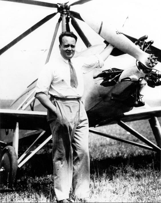
Juan de la Cierva
Photo courtesy Dr. Bruce Charnov
(Open in new window)
Cierva was born in Murcia, Spain, September 21, 1895. He was only eight years old when the Wright brothers first flew on Dec. 17, 1903. He was a young man on his way to becoming a civil engineer when they first demonstrated their machine to the rest of the world in France in 1908. Cierva was intrigued by this new technology and decided to build his own airplane. His first attempt was to rebuild a Sommer biplane. He fitted it with a new engine and made several modifications to the original airplane. When he completed the project in 1912, he named the airplane the BCD-1 El Cangrejo, Spanish for the BCD-1 Crab.
BCD-1 Cangrejo
Photo courtesy Dr. Bruce Charnov
(Open in new window)
The plane flew well and was considered to be the first Spanish built airplane. Cierva's second attempt was the BCD-2, a small monoplane, which he built in 1913. It did not fly as well as the BCD-1 and crashed. It was rebuilt, but crashed again. The design was abandoned. Cierva's third and final airplane design was the C-3. It was for a Spanish military competition announced in September of 1918. The C-3 was entered into the bomber division of the contest. The plane was a large tri-motor biplane, and was completed in May of 1919. It flew well, but in one of the preliminary tests the pilot flew the plane too slow and it stalled. The plane was wrecked, but the pilot escaped without serious injury. This crash disappointed Cierva, and inspired him to think of a better way to fly at low speeds. After tossing a toy helicopter from his parents balcony and studying the flight, Cierva came up with the idea of an autogyro, which he called the autogiro (Notice the spelling with an "i" instead of a "y").
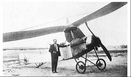
Cierva's first attempt at building an autogyro was the C.1. The C.1 had two counter-rotating rotors to provide lift and by counter-rotating to eliminate torque. A vertical control surface above the rotors was meant to provide lateral control, while a conventional tail rudder and elevators would provide control about the other axes. Unfortunately, this design never flew. Because of the interactions between the two rotors, the top spun faster than the bottom. This upset the balance in lift and torque, causing the machine to tilt to one side. However, when it was tested, in October of 1920, it did demonstrate successfully the principles of autorotation while taxiing on the ground.
After the C.1, Cierva started work on his next design, the C.2. The C.2, was to have only one rotor, consisting of five blades, with duralumin spars. Because of difficulty in obtaining the duralumin, and because of a shortage of funds, work on the C.2 was postponed and Cierva began work on the C.3.
Cierva C.3 Autogyro
Photo courtesy Dr. Bruce Charnov
(Open in new window)
The C.3 was completed in June of 1921. The C.3 had one rotor with three blades. He still had a rudder and elevator for yaw and pitch control, but for lateral control he tried collective pitch variation. This refers to changing the angle of all the different blades at the same time. However this design proved to be impractical, and the C.3 only achieved brief hops of a few inches off the ground.
Once done with the C.3, Cierva went back to the C.2. The C.2 was finally completed early in 1922. It had similar controls to the C.3. It achieved slightly better lateral control, and short hops of a few feet above the ground, but still couldn't maintain sustained flight.
One of the problems with Cierva's three designs up to this point was that the rotor was rigid. This created two problems. First was that it created a gyroscopic effect. As soon as the aircraft tried to move, this effect would cause the aircraft to tilt. The other problem came from unbalanced lift. As the rotor was spinning, one side would be moving the same way the aircraft was moving, increasing the relative wind speed, while the other side would be moving opposite the direction the aircraft was moving, decreasing the relative wind speed. The side with the higher relative wind speed would have a higher lift than the side with lower relative wind speed, causing the aircraft to tilt. Cierva came up with a solution to this problem while watching an opera. One of the props for the opera was a windmill with hinged blades. Cierva decided to use hinges in his rotor designs. This allowed the blades to rise and fall depending on what direction they were moving in. The blades moving with the aircraft rose because of the higher lift, but this also served to decrease their angle of attack. The blades traveling in the opposite direction of they autogyro would fall because of the lower lift, serving to increase their angle of attack. The combination of the rising and falling action, which came to be known as flapping, and the increase and decease this had on the angle of attack served to balance the lifts created on each side of the aircraft. The hinged blades also eliminated the gyroscopic effect caused by the rigid blades.
Cierva's next design, the C.4, incorporated these hinged rotors. For lateral control, ailerons were mounted on outriggers to the side of the aircraft. Yaw and pitch control still came from a rudder and elevators. On January 17, 1923, the C.4 flew, marking the first controlled flight of an autogyro. The C.4 also demonstrated the autogyro's safety in low speed flight. On January 20, three days after its first flight, the autogiro went into a steep nose-up attitude after an engine failure at about 25-35 ft. In an airplane, this would have almost certainly resulted in an almost unrecoverable stall. But the autogyro just descended gently to the ground without damage to the machine or injury to the pilot. This low speed safety was demonstrated even more dramatically on January 16, 1925, when another design, the C.6, lost power after take-off at about 150-200 ft. The pilot was still able to turn the autogyro around and bring it in for a safe landing, with only slight damage to the machine. This maneuver would have been much more difficult in an airplane, and quite possibly could have led to a worse accident.
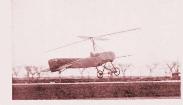
Cierva C.4 Autogyro
Photos courtesy Dr. Bruce Charnov
Open in new window:
1,
2,
3,
4,
5
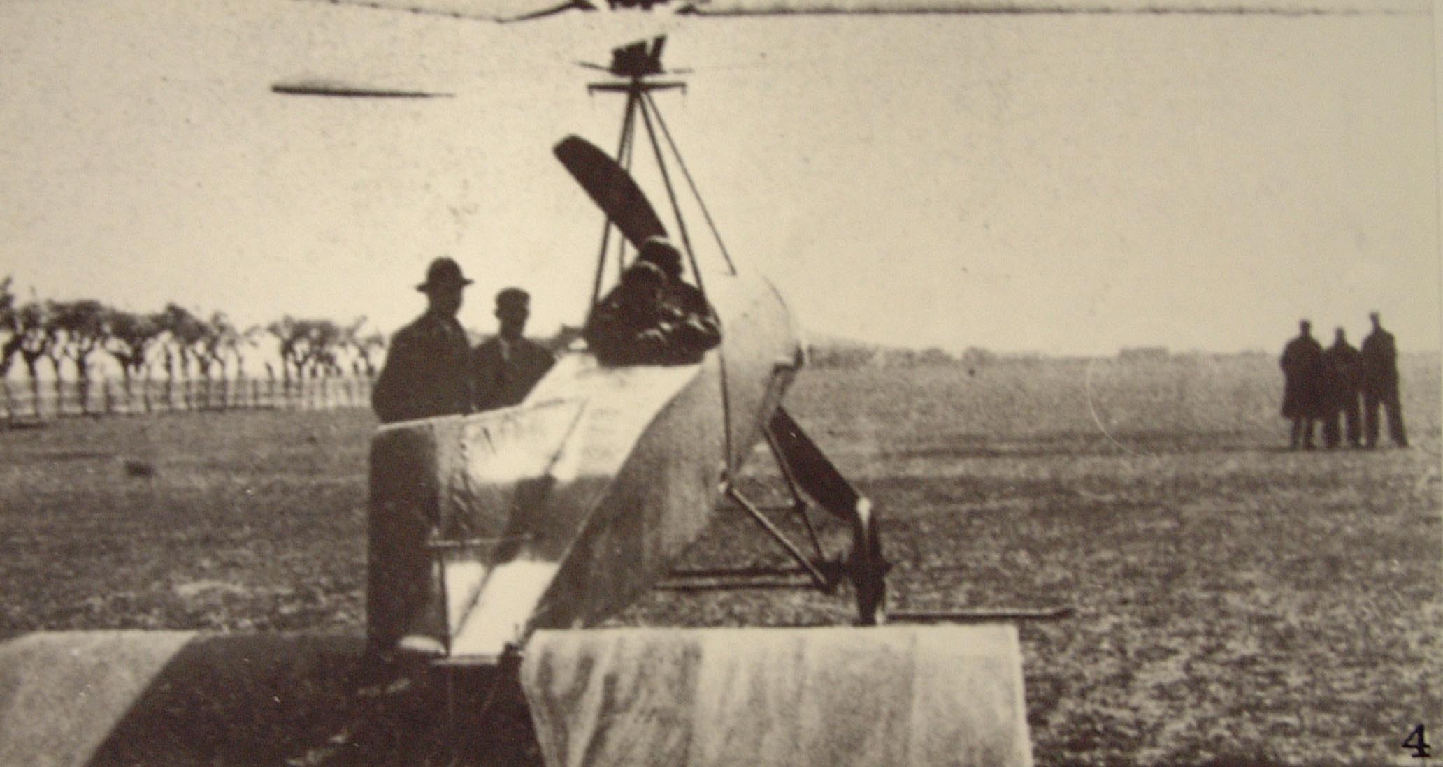
Another problem with early autogyros was rotor spin-up. To achieve autorotation, the rotor had to be spun to a minimum speed before the aircraft began moving. In early autogyros, this was achieved mainly in four ways, spinning the rotor by hand if the rotor was small enough, or if it was bigger, with a team of horses, a team of people, or by connecting it to a car engine through a drive shaft. This need for an external source to spin the rotor kept the autogyro from being a self sufficient machine capable of working anywhere. Cierva's solution for this problem was to design the tail in such a way that it would deflect the slipstream from the propeller up into the rotor. This deflected wind would cause the rotor to spin up. It was achieved simply by adding flaps to the tail that angled upwards. This design was known as a scorpion tail. He tested this idea on a C.19 in 1929. The problem was that the tail did not deflect enough wind. The rotor did spun some, but not to the minimum speed needed for takeoff. A short takeoff run was still needed to spin the rotor the rest of the way. Another method used to solve the problem of rotor spin-up was, instead of connecting a drive shaft to a car, just connect it right to the autogyro's engine. The first attempt to do this was in a modified C.11 early in 1930. A drive shaft was connected to the engine through a clutch. Unfortunately, this mechanism weighed about 165 lb. and was too heavy for the autogyro to fly. An improved clutch and drive shaft system was introduced late in 1930. It was first used in April 1931 on the PCA-2, an autogyro developed by Harold Pitcairn, who had the licensing rights for Cierva's invention in the United States. The drive shaft and clutch system wasn't used on a Cierva design until almost a year later in March of 1932 on the C.19. This new design worked well on both the PCA-2 and the C.19, and became the dominant style of spin-up in all later models of autogyros where the rotor was too large to be spun by hand.
The next major advance in autogyros came on August 5, 1931. This was the first flight of the Wilford WRK. This new autogyro replaced the hinged rotors with a rigid rotor with cyclic pitch variation. Cyclic pitch variation is a method where the pitch of the blades is changed as they spin. The pitch is lowered when they are moving in the direction of the aircraft, and raised when they are moving in the opposite direction. This does the same thing as flapping to balance the lift created by the blades. The WRK was the first autogyro to successfully fly with a rigid rotor.
Earlier in this paper, it was stated that autogyros have the potential for vertical take off and landing. Although all the autogyros discussed so far have been capable of vertical landings at least in an emergency, they have also all needed some minimum takeoff run. But, if the rotor was powered before take off to make it spin at the minimum speed for autorotation, why not just continue to power it to a higher speed and take off from the lift created that way. That is exactly what happened. In August of 1933, experiments were begun on a C.30 in this new method of takeoff, which came to be known as a jump takeoff. These first experiments were promising, but not satisfactory. Spinning the rotor on the ground caused too much vibration, and the aircraft was only capable of making low jumps. By October 28, 1934, after over a year of experimenting and refining, the C.30 finally made a successful jump takeoff. Many later autogyros were also designed for jump takeoffs, most using the same method as the C.30. A few later autogyros had tip driven motors where either a jet or a rocket was put at the end of each rotor blade to spin the rotor that way.
Cierva C.30 Autogyro
Photo courtesy Dr. Bruce Charnov
(Open in new window)
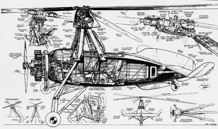
The C.30, besides being the first autogyro to make a successful jump takeoff, was notable for another aspect as well. It was the first autogyro to use direct control. Direct control was a method where the pilot tilted the rotor instead of a rudder and ailerons. This greatly simplified the control of the aircraft, as well as the design. A pilot now had one control for yaw, pitch, and roll, and designers only needed to design that one control. In the C.30 and later autogyros of comparable size, this consisted of a bar connected directly to the rotor hub that extended into the cockpit. For larger machines, the controls of the pilot were mechanically linked to the rotor hub. The C.30 also proved to be the most popular production autogyro ever designed, with more than 180 of them being built.
On June 26, 1935, the Breguet-Dorand 314 was the first successful helicopter to fly. It incorporated many of the features developed for autogyros, such as collective and cyclic pitch control. On December 8, 1941, Igor Sikorsky's V.S.300 flew, another of the first successful helicopters. The V.S.300 was only a test aircraft, but led to the VS-316, a more refined helicopter using the same principles. The U.S. Army ordered the VS-316, and 400 of these aircraft were produced along with the R-5 and R-6, two other Sikorsky helicopters of similar design.
Why Autogyros Weren't Accepted
At this point we can ask the question of why autogyros were never widely accepted. Just about every aviation historian has their own answers to this question, but here is this author's opinion. Early autogyros, although they had a higher speed envelope than airplanes, had a higher drag and so were not as efficient at higher speeds, and absolutely could not attain the maximum speeds of the faster airplanes. Also, the early autogyros did not have the vertical takeoff and landing capabilities that would have made them more attractive to potential buyers. When the C.30 finally demonstrated a successful jump takeoff in 1934, it was less than a year until the first successful helicopter flew, and only a few more years until the very successful Sikorsky V.S.300 and VS-316. Although helicopters had a smaller speed envelope than autogyros, they were capable of hovering, and their envelope could fill the role that airplanes couldn't. In other words, anything an autogyro could do could be done by another aircraft. Also, Cierva, who was doing most of the development of autogyros, was funding much of the development on his own. When the army ordered the VS-316, that money went in to Sikorsky's company. This gave Sikorsky the funding for development that Cierva was running out of. Without the money, Cierva just couldn't fund the research. And then, on December 9, 1936, Cierva was killed in a plane crash (a DC-2 operated by KLM). He was only 41 years old. There were other people developing autogyros, but Cierva had been one of the main driving forces behind the movement. Much was lost when he was killed.
Another factor that kept the autogyro from being accepted was purely psychological. Even though helicopters weren't successful until 1935, they had been under development for as long as airplanes. The general public knew about helicopters, and understood the principle of a powered rotor. Autogyros had an unpowered rotor that spun due to aerodynamic forces. Most people did not understand how it worked and so did not trust it. Although it is actually safer than either helicopters or airplanes, people did not realize this. They wanted something powered.
Autogyros After Helicopters
After helicopters flew successfully and the companies that designed them got military grants for further research, the autogyro was pretty much abandoned. Except for a few concepts and only a handful of attempts at civil designs, autogyros were kept alive only as home built aircraft, and that mostly as ultralights. Recently, there have been two companies to resurrect the idea of the autogyro, Groen Brothers and CarterCopter.
The Groen Brothers design is the more conventional of the two. The unique innovation of the Groen Brothers machine is that it is using ram jets at the tips of its rotor blades to power them for spin up. Ram jets are not very efficient engines, but they will only need to be run for ten to fifteen seconds, so efficiency is not much of an issue. The ram jets will spin the rotor fast enough to enable the machine to take off vertically. Their autogyro will also use a collective pitch control to help reduce drag. It is being marketed to corporations that currently use helicopters, or can't quite afford helicopters, to travel from rooftops in cities. These corporations really have no need for hover, they just need to be able to take off and land vertically. The autogyro can do this faster and for less money than a helicopter. They are also trying to market it to organizations that only need low speed flight and not complete hover. In fact, most observation of stationary objects done by a helicopter is done by flying above it in slow circles, not just hovering.
The CarterCopter is more of a hybrid between an airplane and an autogyro. The rotor will be spun up with a conventional drive shaft and clutch system, but the rotors will have 60 pound weights at their tips. This will cause the rotor to function as a flywheel for the jump takeoff. It also allows the rotor to be slowed down in cruise and still maintain enough rigidity from centrifugal force to be stable. Once flying, the pitch on the rotor blades will be lowered as much as possible to reduce the drag created by them to as little as possible. The lift will come from conventional airplane wings mounted on the sides of the aircraft. The company is predicting that the CarterCopter could surpass the performance of all aircraft except jet propelled airplanes and spacecraft. This includes helicopters, all previous autogyros, piston powered prop planes, and turboprop airplanes. With a turboprop engine, the craft should be able to fly 400 mph at 45,000 feet. A modified propeller version could be able to fly at 70,000 ft., while a jet powered version could fly 500 mph or more. A specially modified version of the aircraft should be able to fly 25,500 miles on one tank of gas, which would allow it to equal the Voyager's round the world flight of 1986, but with a vertical takeoff and landing. With its performance, the CarterCopter would not only be able to fill the roles the Groen Brothers would like to fill, but also those currently belonging to propeller driven aircraft. (In the interest of full disclosure, it should be stated that the author is an employee of Carter Aviation Technologies - although the CarterCopter was included in the original version of this paper while the author was still a student.)
Concluding Remarks
Autogyros were the first successful rotary wing aircraft to fly. They marked a departure from conventional fixed wing aircraft and an attempt to fill a role that airplanes couldn't. They can fly slowly due to a phenomenon known as autorotation, where the rotor is unpowered and is made to spin by aerodynamic forces. Autorotation allowed the wings to move faster than the aircraft. Although autogyros were never widely accepted by the public, the military, nor aircraft companies, they were very important in the development of the helicopter. Many technologies essential for practical helicopters were first developed for the autogyro. If Cierva had not pursued the autogyro, it almost certainly would have delayed the development of the helicopter, maybe even for decades. After the introduction of the first successful helicopters, autogyros were largely forgotten except as kit aircraft and ultralights. Recently, two companies, Groen Brothers and CarterCopter, have brought back the autogyro using modern technologies. Neither plans to replace the helicopter entirely, only in places where low speed flight or vertical take off and landing are all that are needed. Perhaps, if these companies have their way, the future will be more kind to the autogyro than has the past.
References
About Gyroplanes. Internet Resource: http://www.saskia.com/~zlinak/about-copters.htm (No Longer Available)
Brie, Reginald. The Autogiro and How to Fly It. Bath: Pitman Press, 1934
Brooks, Peter W. Cierva Autogiros. Washington: Smithsonian Institution Press, 1988
CarterCopters, Inc. Internet Resource: http://www.cartercopters.com/
Garvey, William. "Gyrocopters Grow Up." Popular Mechanics, June 1996
The Groen Brothers Aviation Home Page. Internet Resource: http://www.groenbros.com/
Rotorcraft Page. Internet Resource: http://www.rotorcraft.com
Additional Information
As was stated at the top of this page, this paper was originally intended mainly as a description of how autogyros works, as well as an account of the history of autogyros. It only covers this history up through the 1930's. However, now that I have put it on the Internet, it is being read by far more people than I had ever imagined would read it. I have received many positive comments on the paper from these people, and I have also received comments on some of the shortcomings of the paper, specifically in the area of the state of current autogyros. Although autogyros never enjoyed the success of airplanes and helicopters as practical commercial machines, they have enjoyed much success as homebuilt and kit aircraft. There are several companies that make autogyros now, and have been doing so for many years. The best sites to learn about current homebuilt autogyros are www.rotorcraft.com or the Popular Rotorcraft Association (PRA) Homepage
I didn't fully explain why autogyros can't fly fast in this essay. So, I've added another essay explaining it. It can be found at Rotorcraft Limitations.
Another area where my essay could use a little more information is in explaining why autogyros never caught on. Paul Bergen Abbott, previous Editor/Publisher of Rotorcraft Magazine sent me the following in an e-mail:
Your explanation of the demise of autogyros is excellent. This is a subject I've been interested in for some time, since, from the vantage point of 1996, it looks like the world made a hasty decision in abandoning the gyro. I think there were two other factors involved, besides the ones you mentioned: One is that as the world began moving toward World War II, the rivalry between the United States and Germany grew to a fierce level ... In 1938 Germany demonstrated the Focke-Achgelis F.61 helicopter, a side-by-side-rotor model, by flying it publicly inside a building and making headlines all over the world. This infuriated the powers-that-be in the United States, and soon thereafter the government attention and development funds were shifted entirely to helicopter development. The second other contributing factor was the death of the two motive forces behind gyros: Juan de la Cierva in a plane crash in 1936, and Harold Pitcairn in a handgun accident (some believe it was a suicide).
There's also the fly-off competition that was held between one of the late-model autogyros and a biplane, with the winner to get military funding. The contest was rigged so the gyro couldn't win even though gyros could outperform airplanes at that time (I don't have the details on the top of my mind as to when and what models were involved.)
Related Links
History/General Information:
- Hofstra University Autogiro Conference- Has many autogyro photos in the Galleries section
- Wikipedia Entry on Autogyros
- Popular Rotorcraft Association Home Page
- Rotorcraft Page
- Autogyro.com A site for model autogyros
- Asociación de Amigos de la Aeronáutica- Has a reconstruction of Cierva's C.30
- gyroplanepassion.com- A website, in its own words, "dedicated to all things relating to gyroplanes, autogiro, autogyro, gyrocopter, autogir, autogyre, autozyro, ect." It looks to be especially useful to somebody wanting to own their own autogyro.
- Other Aviation Links
Companies:
I'll specifically recommend Bruce Charnov's, From Autogiro to Gyroplane: The Amazing Survival of an Aviation Technology. I haven't yet read this book cover to cover, but skimming through it it looks very thorough.
Translations
Through the counter at the bottom of this page, and from e-mails I've received, I've noticed that quite a few people are reading this paper from various countries around the world. Unfortunately, the paper is currently only available in English and German. If anyone would want to tackle the problem of translating the paper into another language, I'm sure it would help out those people with a curiosity for autogyros that can't speak English. If you sent me the translation, I could host it on this site, or you could host in on your own site. I just ask that you give me credit, include a link to this page, and send me an e-mail to let me know that you're doing it.
Number of people who have visited this site since 4 Jan, 2002: